Condition monitoring & vibration-based damage detection:
VibSens-PRO Capability:
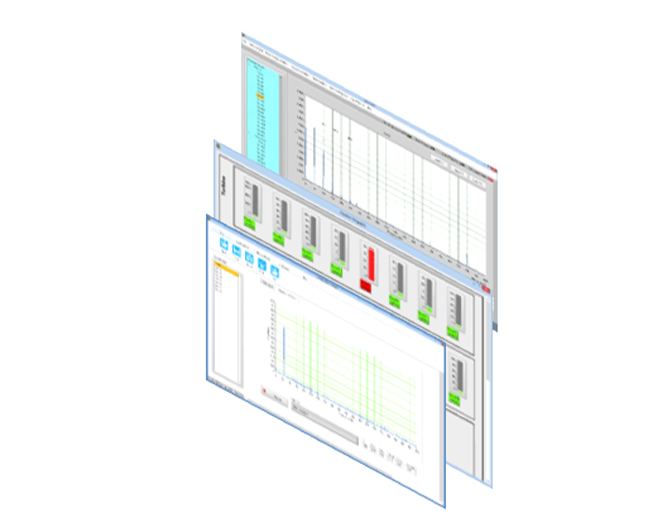
VibSens-Pro software is the base package which can be connected to all the VibSens measurement systems with data acquisition capability. It is a comprehensive tool to perform & train machine condition monitoring and damage detection. VibSens software acquires, stores and analyzes data from sensors. It is capable of transmitting data over local or wide area network. It provides static, dynamic and transient data collection and analysis; such as graphical indication of vibration level, trend, waveform, spectrum, orbit plot, polar plot, waterfall, bode plots, envelope spectrum and much more. Additionally, it can collect process data as 4‐20mA input or digital monitor input via Modbus protocol. It provides an integrated system solution for complete process tests where not only sound and vibration signals but also process parameters such as temperature, flow or pressure is also needed to analyze system response. With its flexibility, it not only can acquire the data from third party measurement hardware but also share its data with third party software and hardware.
Machine Diagnostic Application:
Vibsens-Pro has been developed as a stand-alone application to be used for machinery diagnosis and verification of root cause of vibration problems via on-line &off-line data review and analysis.It contains mostly used functions to provide engineers with a collection of the most beneficial tools.
A brief summary of the functions available in Vibsens comes in the following:
Frequency Spectrum Plots:
Machines can vibrate at many different frequencies simultaneously. These frequencies can be related or unrelated to running speed and include both sub synchronous and super synchronous frequencies. Since these frequencies are associated with the operating condition of the machine, the machinery diagnostician must have some way to determine the frequency content of a vibration signal in order to make an accurate diagnosis. FFT (Fast Fourier Transfer) is used to seize out the frequency contents of a vibration signal. Frequency detection menu in VibSensis has been developed in a way user may choose machine type and then by entering its technical specifications, study if there are machine related symptoms in the spectrum. Machine type analysis available is as follows:
- Gearbox Frequency Analyzer
- Electric Motor
- Pulley-Belt
- Rolling Bearing Frequency Analyzer
- Side band Analyzer
- Harmonic Analyzer
Time signal :
Time waveform is the fundamental graphic presentation of machinery dynamic data. It shows how a single parameter (most often displacement , velocity, or acceleration, but also any other dynamic measurement) from a single transducer changes on a very short time scale, typically a fraction of a second. This is in contrast to trend plots, which display the value of a slowly changing parameter over a much longer time scale,typically hours to months. Moreover, on the bottom part of the graph key parameters like RMS, Peak, Pk-Pk and crest factor are calculated and shown.
Orbit Analysis:
Orbit analysis is a tool used to detect failures like rubs, unbalance,misalignment or oil whip in journal bearing machines. Required are two or thogonally installed proximity probes for time-based orbit plus a trigger signal from a tachometer probe to see the ordered orbit plot.
Trend plot:
The trend plot is a rectangular plot on which the value of a measured parameter is plotted versus time. Trend plots can be used to display any kind of data versus time: Displacement, Velocity, Acceleration,gap voltage (radial or thrust position), rotor speed, and process variables, such as pressure, temperature, flow, or power.Trend plots are used to detect changes in these important parameters. They are used for both long and short term monitoring of machinery in all types of service and are, typically, a kind of a steady state plot. Different overall value types of measurement (RMS, Peak and Pk-Pk) may be used for the plot.
Waterfall plot:
Waterfall plots are designed to display multiple spectra (FFT spectrum) versus time, during run up, run down or constant speed operation. Waterfall plots are 3D plots with time, frequency and amplitude axis. Waterfall plots are commonly used to examine how machine vibration changes with a change in an operating parameter.
-
Modal testing & analysis:
VA-2000 also includes software developed for the measurement of frequency response function during an impact test. It calculates H1, H2 or H3 FRF with Force/exponential, Hanning, Hamming or other user selected windowing functions. Moreover, it calculates and displays coherence, frequency spectrum, and time signal for every input. It can measure natural frequencies, damping ratios and is ready to export FRF files in text or UFF file formats (Real / Imaginary, Magnitude / Phase). FRF measurement files can also be saved in formats compatible with 3rd party modal and operational modal analysis software packages like ICATS™, Artemis™, etc.
Sampling frequency & number of samples is quite flexible and can increase limiting the number of measurement channels from 12K Hz & 36k data points for 24 input channels to 40 KHz & 300K for 3 input channels, which is very useful for measurement of excitation with one modal hammer and response measurement with two to twenty three accelerometers.
It can be used in modal testing and vibration laboratories for training students on how to extract natural frequencies of a structure and compare the natural frequencies with finite element models and analytic solutions. It is useful for experimental model updating used across the industry in R&D departments.
Finite element model updating is a mathematical and experimental approach to make sure that finite element model of a structure is reliable to simulate structure response under different loading conditions. Indeed, it is the main part of verification and validation of numerical models. This process is followed in several steps. Performing experimental tests in the interested range of frequency on the real structure, then frequency response files are analyzed by modal analysis software and natural frequencies, damping ratios and mode shapes should be extracted. A finite element model in a software package is created and modal frequencies & mode shapes are extracted from the software. Results between experimental and simulation are compared and the model is updated in a way to be able to simulate the experimental results.
-
Rigid / flexible rotor balancing:
Unbalance is the most common source of vibration in rotating equipment.Rotor unbalance may be defined as a situation in which the geometric center and the center of mass do not coincide. In reality, these centers never coincide exactly, but the goal of rotor balancing is to reduce the unbalance to the point that machine life is not negatively impacted by the residual unbalance. The balancing technician attempts to bring the center of mass and the geometric center to the same point or close enough to meet a predetermined balance standard so there will always be some residual unbalance. There are two types of balancing processes rigid rotor balancing and flexible rotor balancing.
Rigid rotor balancing:
A rotor that operates at a rotational speed below 70 percent of its critical speed is considered to be a rigid rotor. The critical speed is the speed at which resonance occurs by exciting its natural frequency. Ninety percent or more of rotors are rigid. Rigid rotors can be corrected in one or two correction planes. After the correction, the residual unbalance does not change significantly at any speed up to the maximum service speed. Based on the ratio of length to diameter of rigid rotors are balanced in one or two planes.
In single plane balancing vibration measurement and unbalance correction are both made in just one point and plane while in two plane balancing unbalance correction and measurement are made at two points and planes.Balancing procedure includes an initial measurement, then adding a trial mass and measurement of vibrations
and the software calculates the best quantity and place to put the balancing weight and finally measuring the vibrations to check the final value of vibrations and comparison to the initial state.After installing the final balancing mass, comparison of before and after balancing procedure is shown in a page to evaluate the effectiveness of balancing on overall vibration of the bearing. As shown in above unbalance has reduced vibration of bearing from 0.029 g to 0.004 g i.e. nearly 80% of vibration has been eliminated.
Flexible rotor balancing:
Flexible rotor is defined as a rotor which exhibits considerable lateral deformation near or below its maximum design speed, in other words flexible rotor is a rotor which passes or is operated near one or more of its lateral critical speeds. Flexible rotors cannot be just balanced in two planes and would need to be balanced in the vicinity of all critical speeds below the maximum design speed of the rotor. It is also often necessary to balance a flexible rotor at its operating speed. Therefore balancing flexible rotors needs special tools such as a vibration analyzer capable of phase and amplitude measurement. Moreover it should be able to plot amplitude vs. speed, phase vs. speed and amplitude vs. phase graphs also known as polar plot and Bode plot.
Many of the power generation gas and steam turbines are flexible and need flexible rotor balancing. The same applies to multi stage high speed gas compressors. While rigid rotor balancing is usually performed with accelerometers, flexible rotor balancing is performed with proximity probe displacement transducers.
VA-2000 is capable of measurements needed for flexible balancing in two ways installation of new transducers or getting connected to a protection system and get data from buffered output of protection system.
-
Acoustics Analysis
Vibsens-Pro Sound option is an application developed to analyze sound files recorded by VA-2000 measurement system. Acoustic analysis such as frequency spectrum, sound harshness, loudness, roughness analysis is performed in this software. Octave band analysis, demodulation and sound level measurement is also included in the software.
One of the key parts in today’s world in design of machinery is about noise and acoustics emission. One of the things customers care in selection of a product is how much noise it makes. So manufacturers are paying more & more attention to the sound of their products nowadays. For a thorough study on how to decrease noise of a product, one needs a sound analyzer. VA-2000 is a cost effective and comprehensive solution for sound analysis. Another application of sound analysis is as a technique for damage detection and to compare intensity and frequency content of sound of an old machine with a healthy new one.
There has been standards & guidelines published for the evaluation and analysis of acoustics emission of a machine. VA-2000 has features for this job and moreover, it can export signals in WAV file format for further analysis in other 3rd party software.
It can take up to 24 microphones for analysis with 12 KHZ sampling frequency, of course in many applications it is not needed and if number of microphones used as input is limited to three, it enables the user to perform the analysis with 40 KHz which contains all the audio bandwidth of human ear.
- Some of the functions for sound analysis is as follows:
- Time signal and frequency spectrum
- Determination of sound parameters such as loudness, harshness & roughness according to ISO532B / DIN 45631
-
NVH acceptance tests for special parts & rotary machines
Many standards & guidelines have been developed for FAT (field acceptance test) and SAT (site acceptance test) of rotating machinery like ISO 10816, ISO 7919 etc. which forces the manufacturers of rotary machines to have a sound & vibration test lab to be able to test and verify their products at the end of the production line and as a quality check procedure.
These manufacturers based on their product need a sophisticated lab to be equipped with sensors and measurement required for performing these validation tests. VibSens VA-2000 can be readily applied in this field. An example is discussed in the following. Manufacturers of the following products all fall in this category.
- Pumps
- Compressors
- Gearboxes
- Turbines
- Electrical motors
Natural frequency of solid structures is a function of geometry & material specs. One of the growing uses of frequency analysis and natural frequency tests is as an end of production line quality control test. Products are excited by modal exciters and the natural frequency of the product under test is compared to the natural frequency of the proof product. Vibration test rig is developed for comparison of parts manufactured with a proof sample as a QC planning at the final stage. Difference more than a determined value in frequency measured from the response upper or lower than one of the interested natural frequencies in the interested range could show some geometric or material inconsistency and lead to the rejection of the product.
This application is much useful for the companies which produce the following parts:
- Turbine / compressor blades
- Bearing manufacturers
- Gear manufacturers
- Automotive parts